Operating a Shift Register 10 Steps Circuit Diagram In order to save on pins I am using a shift register to control the columns. This way I can control an almost unlimited number of columns with just four microcontroller pins. It is possible to use only three if the Enable Output pin is tied directly to voltage. I have selected the HEF4794 LED driver with shift register.
5.1 Using the 74HC595 Shift Register . In this lesson, we'll learn how to use the 74HC595 shift register to control multiple LEDs with just a few GPIO pins on the Raspberry Pi Pico 2. The 74HC595 is an integrated circuit (IC) that allows you to expand the number of digital outputs using a serial input.

LED Matrix Using Shift Registers : 7 Steps (with Pictures ... Circuit Diagram
Code to Control LEDs using the 74HC595 Shift Register. Firstly, it allows you to control multiple outputs using only a few Arduino pins, which is especially useful when you have limited pins available. Secondly, it reduces the amount of wiring required, making your project more organized and easier to manage. 🚀 In this tutorial, we'll learn how to use the 74HC595 shift register with an Arduino Nano to control 10 LEDs with different lighting modes. This method hel
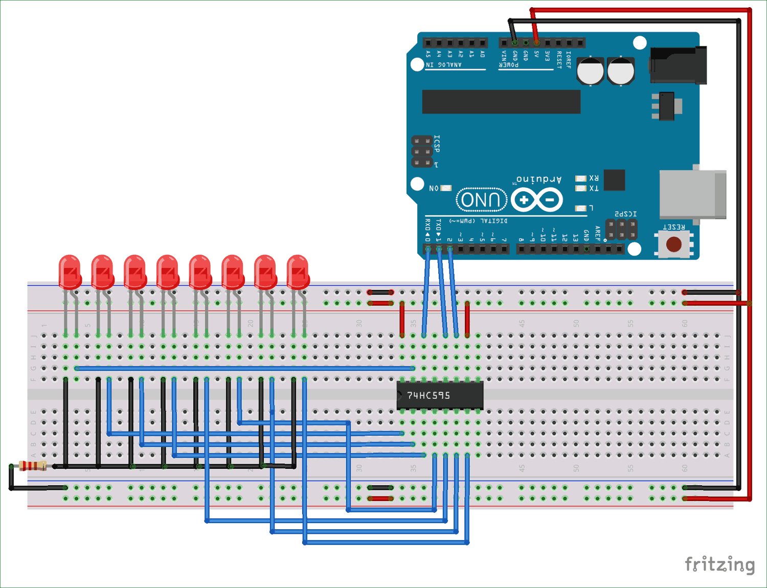
Fig: 74HC595 Shift Register. The 74HC595 is an 8-bit serial-in, parallel-out shift register.It is a popular IC used for expanding the number of output pins on a microcontroller. By using a shift register like the 74HC595, you can control multiple outputs, such as LEDs, with just a few pins from your microcontroller.This makes it ideal for projects where the microcontroller's pins are limited

More Arduino Outputs With 74HC595 Shift Register Circuit Diagram
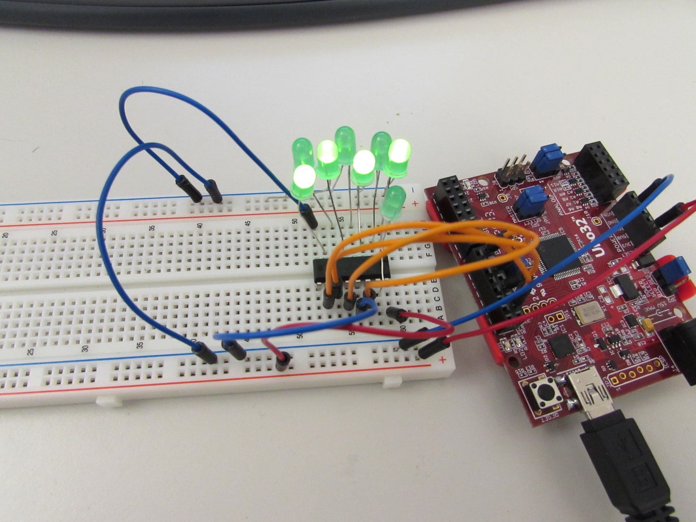
Using a Shift Register to Control a Bunch of LEDs. Shift registers are very useful tools; using a few pins connected to a shift register, we can increase the number of output data pins that are available to us. In this experiment, we'll be using a shift register to control eight LEDs, but we'll only be using three pins from the ATmega.
