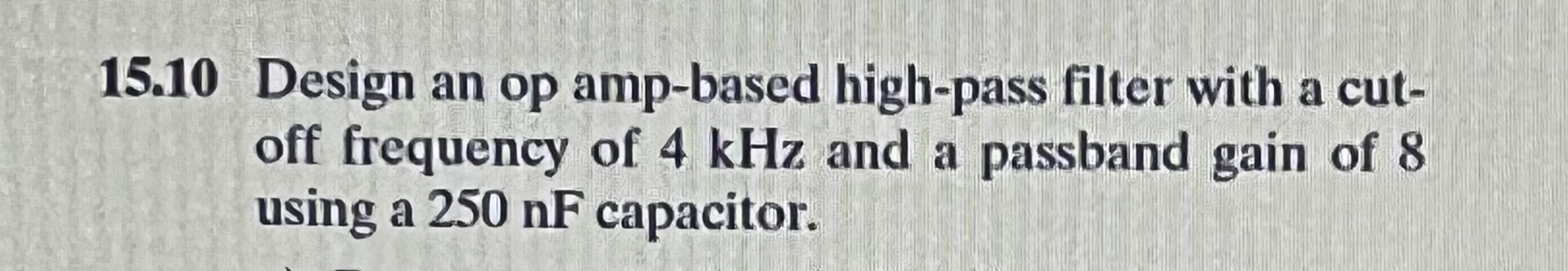
Solved 510 Design an op ampbased highpass filter with a Circuit Diagram Step-by-step design of Active low pass filter using Op Amplifier. This circuit is an op-amp-RC resonator: it produces resonance using only resistance, capacitance, and amplification. We could use this circuit to replace the inductor in a second-order RLC (resistor-inductor-capacitor) filter, but instead, we'll look at a simpler and more compact topology known as the Sallen-Key filter. Second-Order Active
Active Low Pass Filter Example No1. Design a non-inverting active low pass filter circuit that has a gain of ten at low frequencies, a high frequency cut-off or corner frequency of 159Hz and an input impedance of 10KΩ. The voltage gain of a non-inverting operational amplifier is given as: Active Low-Pass Filter Design Jim Karki AAP Precision Analog ABSTRACT This report focuses on active low-pass filter design using operational amplifiers. Low-pass filters are commonly used to implement anti-aliasing filters in data acquisition systems. Design of second-order filters is the main topic of consideration. Circuit diagrams and their building blocks, such as low-pass filters and op amps, may sound complex, but the basics are easy to understand and apply. Op amps are the backbone of many audio circuits, and low-pass filters are one of the most common op amp applications.
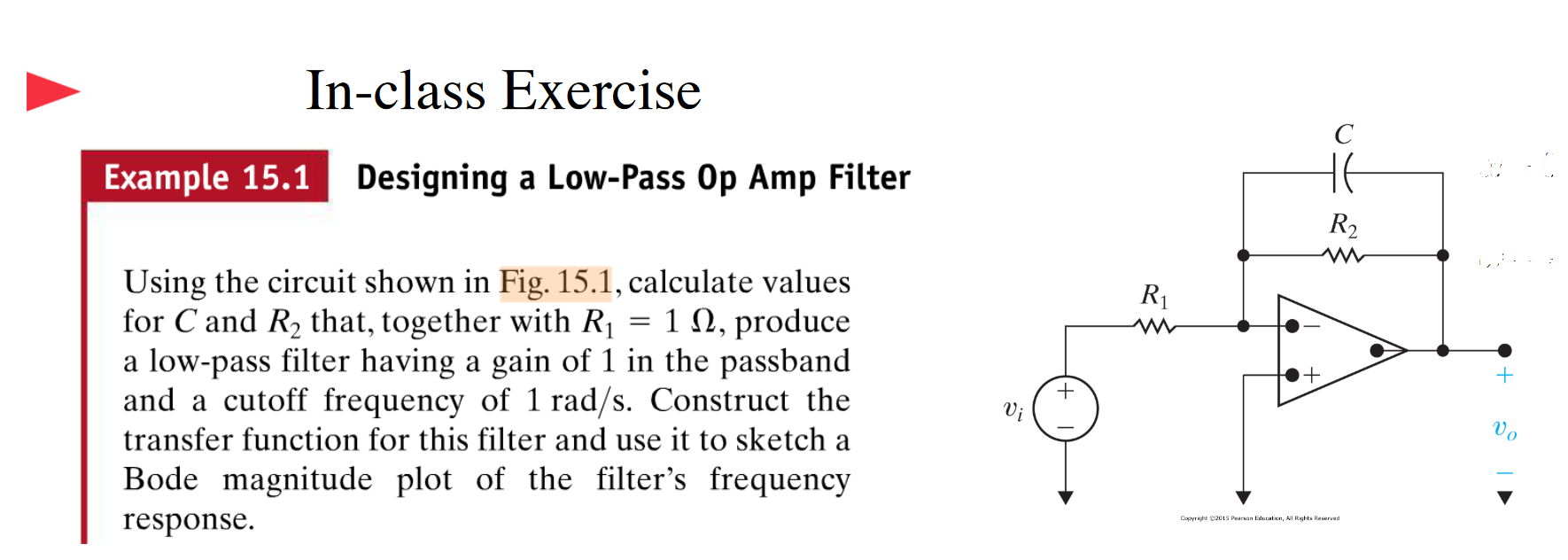
Active low pass filter using Op Amplifier Circuit Diagram
Hi, thanks for watching our video about active filters! In this video we'll walk you through:- How to design, simulate and build active opamp filters- Using So as you can see, there a number of factors that go into creating a low pass filter with an op amp. If you are dealing with high-frequency signals, then it's best to use a much higher-speed op amp than the LM741. For relatively low frequencies, it should suffice. And this is how a low pass filter circuit can be an op amp. Related Resources
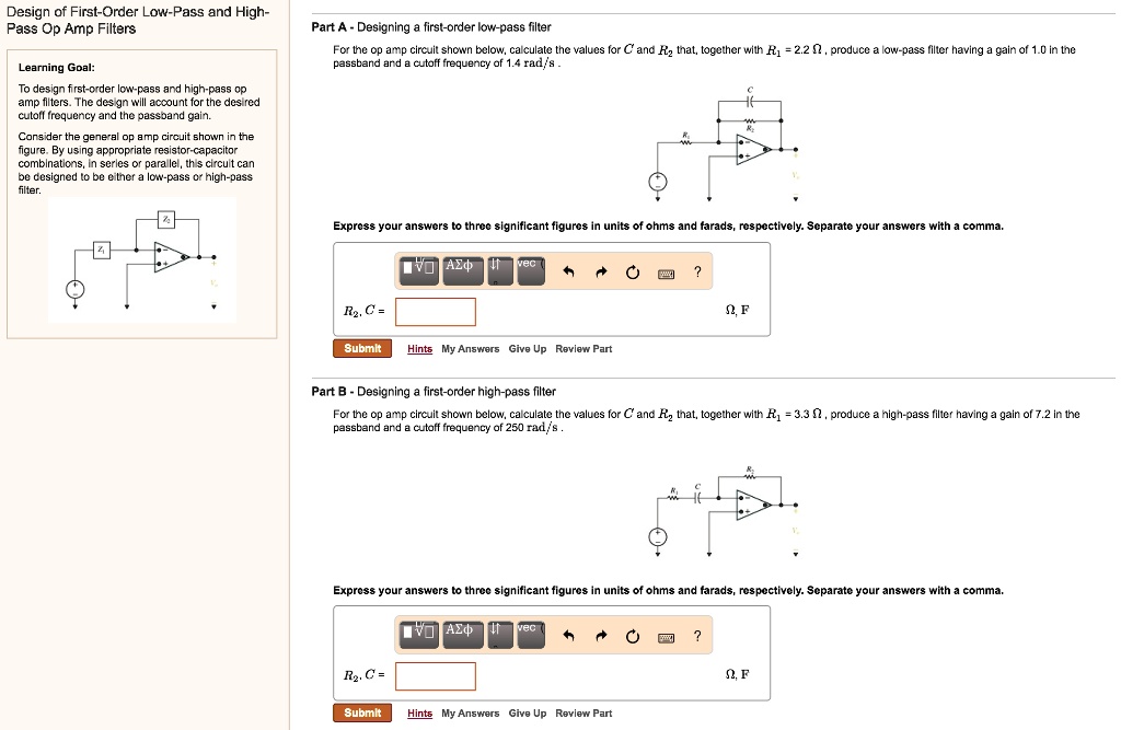
1. To design a First Order Low Pass OR a High Pass Filter using an Op-Amp and a designated capacitor as the frequency determining component. 2. Build the low-pass or high-pass filter of your design and check its frequency response. Drive the circuit with a sine wave and record input (constant) and output voltage for different frequencies.